Audio Compressor Ratio Explained: How To Choose The Best Ratio Based on a Peak Target
When I talk about compressor ratio, I define it plainly as the slope of the compressor’s input-to-output transfer curve above the threshold, expressed as dB in to dB out. Set 2:1 and every 2 dB the signal rises above the threshold turns into 1 dB at the output.
Here’s the part I always want you to hold onto as you read. Ratio works alongside threshold placement, knee shape, detector behavior, and attack and release. If any one of those changes, the same ratio number can lead to a different result on real audio. So I treat ratio as a control that shapes overshoot, then I verify the outcome with meters, level-matched A-B comparisons, and repeatable tests.
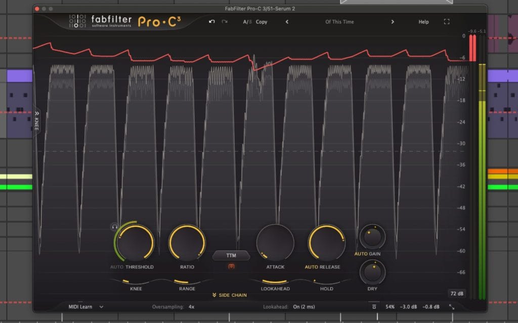
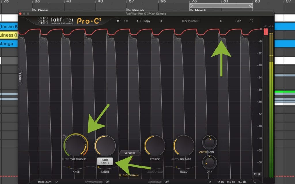
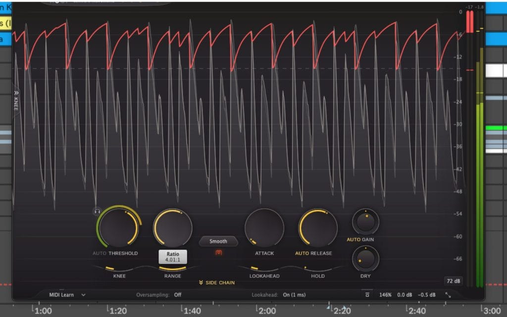
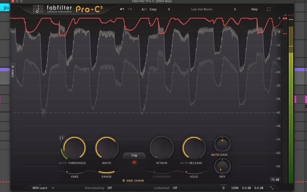
I wanted to have this article stay practical but I’ll admit it gets a bit into the weeds. I start with the math that people quote, then I connect that math to the way compressors actually behave once time and detection get involved. Luckily, Fab Filter’s Pro-C 3 just dropped so let’s use its beatuful UI as the backdrop for all the examples we’re about ot show.
Snag The Compressor Here, it’s legit the GOAT of all compressors.
What compressor ratio means in dB math
I alwys like to start from one basic and consistent reference point: everything is measured in dB above threshold unless I say otherwise. That single rule removes a lot of confusion.
Above threshold, the static model is straightforward. Output change equals input change divided by the ratio.
Two equations cover most use cases. These assume the input is above the threshold.
Output level:
Output = Threshold + (Input – Threshold) / Ratio
Gain reduction amount:
Gain Reduction = Input – Output
Gain Reduction = (1 – 1/Ratio) x (Input – Threshold)
Let me walk that through with a simple example, and just go over it a bit more.
Say the threshold sits at -20 dBFS and an input peak reaches -16 dBFS.
The peak is 4 dB above threshold. With a 4:1 ratio, that 4 dB overshoot gets divided by 4, so you end up with 1 dB of overshoot at the output. That puts the output peak at -19 dBFS.
I also like checking the same idea with a second number because it keeps the slope concept clear. If a signal overshoots threshold by 9 dB and you set 2:1, the static model predicts 4.5 dB of overshoot at the output. That is the baseline expectation before attack and release reshape anything.
One detail that matters: ratio only applies to the portion of the signal above threshold. That means threshold placement often determines how much compression happens across a phrase, a drum hit, or a mix section. A gentler ratio with a lower threshold can lead to more total gain reduction across time than a steeper ratio with a higher threshold, because the compressor spends more time working.
A few edge cases keep the concept clean.
A 1:1 ratio means no compression action. An infinite ratio creates a hard ceiling in transfer-curve terms. Tools labeled as limiters often include design features that change behavior beyond ratio, so matching ratio numbers across processors does not guarantee matching results.
If you’re feeling overwhelmed a bit at this point in the article, I’d recommend taking a look at Izotope’s definitive guide on mixing for beginners. No shade, this article gets heavily into the weeds of things, and if you’re looking for a basic catch-up on compression, mixing, etc, this article here is the move for you.
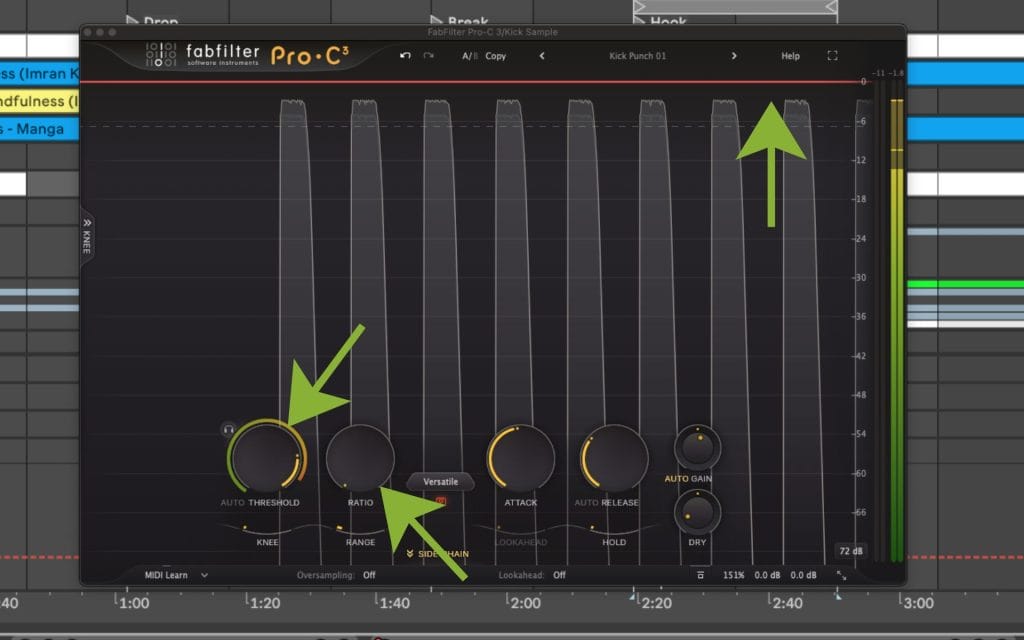
How I pick ratio from a target, instead of guessing
A lot of people reach for ratio like it is a “more control” knob, then they wonder why the meter hardly moves or the sound hardly changes. I think I would prefer starting with a target that is easy to state.
Let’s break down the method I use when I already know where I want peaks to land after compression.
Let X equal the input overshoot above threshold.
Let Y equal the desired output overshoot above threshold.
Ratio = X / Y.
Okay, so now for another example – sory if it’s starting to feel repetitive but sometimes it just take a lot of drilling down for these things to stick.
Threshold = -12 dBFS.
Input peak = -6 dBFS.
That is X = 6 dB above threshold.
If you want that peak to land at -9 dBFS, then Y = 3 dB above threshold.
Ratio = 6 / 3 = 2:1.
This approach stays useful any time you are trying to control peaks ahead of saturation, clipping, or a limiter later in the chain. You set a threshold that makes sense for the material, then you choose a ratio that turns the overshoot into the overshoot you want.
A quick mental reference for overshoot
Here is a fast reference I keep in my head because it helps me predict outcomes before I start turning other knobs.
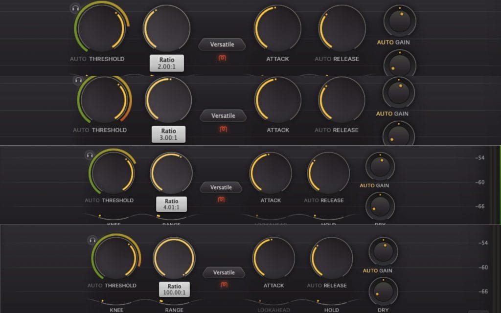
If the input rises 6 dB above threshold in the static model:
At 2:1, the output overshoot becomes 3 dB.
At 3:1, the output overshoot becomes 2 dB.
At 4:1, the output overshoot becomes 1.5 dB.
At infinite ratio, the output overshoot becomes 0 dB.
That is the clean baseline. In a session, the next section is where reality shows up.
Why the ratio math stops matching what you see on real audio
Real compressors apply gain reduction through an envelope shaped by attack and release. That envelope can miss fast peaks, or it can remain active after the loud moment has passed. So you can set a high ratio and still see transients slip through when attack is slow enough.
This is also why ratio settings feel inconsistent across sources. A drum transient might cross threshold for a few milliseconds, while a vocal phrase can remain above threshold for a longer window. Same ratio, different time profile, different behavior.
Knee shape changes how ratio enters the picture. A soft knee transitions into the selected ratio across a region around the threshold. Compression starts gradually, then reaches the selected ratio as the signal rises further. Depending on the design, you can see gain reduction begin earlier than you expect, even when the displayed threshold looks untouched.
Detector behavior matters as much as ratio. Peak detectors react fast to short peaks. RMS-style detectors respond to average level across a window. Program-dependent designs shift timing based on the incoming signal. Put the same ratio value on different detector designs and the gain reduction pattern can change in a way you can see on the meter and hear in the level stability.
Sidechain filtering changes how often the ratio gets applied in practice. When I high-pass the detector, low-frequency energy triggers less gain reduction. That keeps bass-heavy content from pushing the compressor into constant reduction on a vocal or a bus, while the ratio setting stays the same.
Metering context influences ratio decisions too. Peak meters tell you about peak containment. LUFS and short-term loudness tell you about density over time. VU-style meters tell you about average behavior. If you only watch one meter, ratio decisions can drift fast. I usually keep an eye on peak level and short-term loudness, then I interpret the gain reduction meter in that context.
Selected ratio versus effective ratio
The number you dial in is the selected ratio. The slope you actually get across a real signal is the effective ratio once knee shape, detector integration, attack, release, and program-dependent timing are in play.
If you want a clean check, use a steady sine tone. Turn off auto makeup gain. Disable program-dependent timing if the processor allows it. Set a threshold, then raise the input level in 1 dB steps above threshold while logging the output. The measured slope across that range shows you the effective ratio you are getting. This also exposes soft knee behavior quickly, because the slope changes around threshold instead of switching at one point.
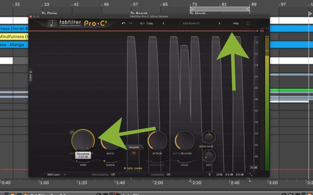
One control that can make ratio feel broken
Some compressors include a Range control or a Max Gain Reduction control that caps attenuation. When that cap is active, ratio changes can look unresponsive because the compressor reaches the cap first. If ratio changes feel like they do nothing, and threshold crossing is obvious, I check for a gain reduction cap before I change anything else.
High ratios and limiter behavior
High ratios can approach limiting behavior in transfer-curve terms, then real-world behavior depends on design. Lookahead changes how much the processor catches fast peaks. True peak detection changes how output peaks are measured and controlled. Oversampling can change how processors handle inter-sample peaks and transient shapes. Detector integration choices change how quickly the processor reacts and how long it holds reduction.
This is why two processors can show the same ratio label and still behave differently at the output. If you evaluate a limiter, test with steady tones and transient material, then confirm behavior with gain reduction metering and output peak readings.
Ratio also shows up in expansion and gating
Some processors use a ratio control in downward expansion and gate-type processing. The label can look familiar while the behavior differs. The reliable check is a transfer curve view when available, and the manual when it is not. That keeps you from assuming the ratio behaves the same way across different processor types.
Ratio starting points by goal, and what I check
Vocals
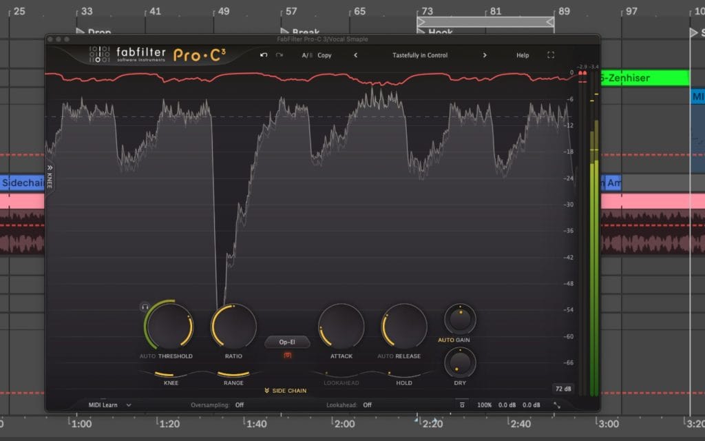
For vocals, I usually start around 2:1 to 4:1. I set threshold so the compressor works during sustained phrases, then I tune release so the gain reduction returns smoothly between lines. Once that is stable, I adjust ratio to control overshoot on peaks, especially plosives and louder consonants. I confirm the result by watching gain reduction movement, peak level, and short-term loudness across a full verse, then I level match and A-B.
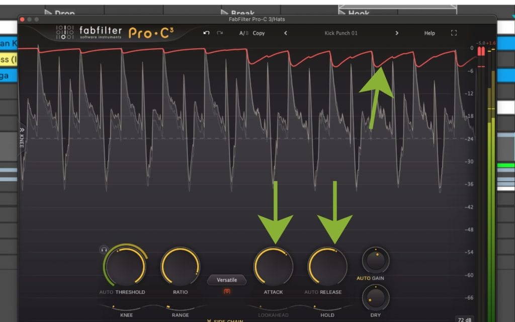
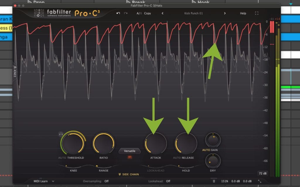
Drums and transient-heavy sources
On drums, ratio ties directly to transient handling, then attack decides how much of the transient remains. A 4:1 ratio with a faster attack contains peaks. A similar ratio with a slower attack allows more of the initial hit through. I compare peak readings before and after compression, then I watch how average level changes, because ratio and attack interact in a way that can shift perceived punch and density fast.
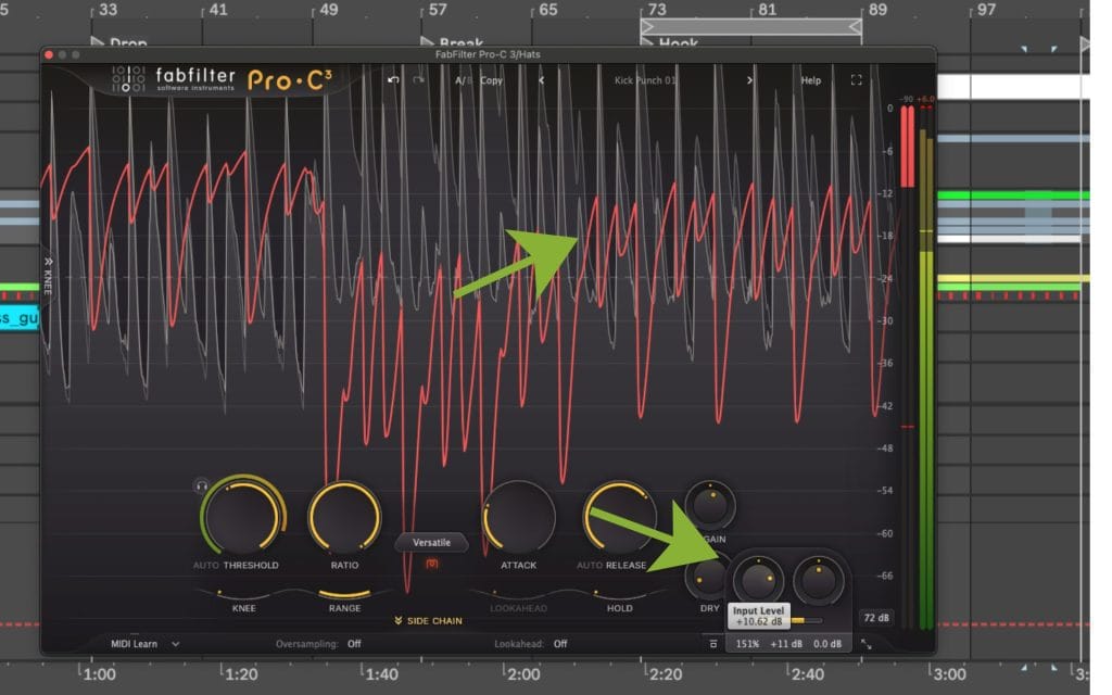
Bass
For bass, I start with modest ratios, then I use sidechain filtering and release tuning to keep low-frequency energy from pulling the compressor into constant reduction. When occasional peaks still need control, I add a second stage with a higher ratio aimed at peak containment, while the first stage handles phrase-to-phrase stability. I keep an eye on gain reduction consistency, because continuous reduction on bass often leads to audible level movement when the release timing misses the groove.
Mix bus
On the mix bus, I start low, usually around 1.5:1 to 2:1. I pick knee behavior and release first, because those controls often decide how smooth the reduction feels across sections. Then I adjust ratio to shape how the bus reacts when the chorus hits and the level rises above threshold. I level match the output, then I watch short-term loudness and peak headroom to confirm the setting supports the goal.
Mastering and peak control
If the goal is strict peak ceiling enforcement, I reach for a limiter and verify true peak behavior, then I use compression earlier for broader level control and crest factor shaping. High ratios on a compressor can move toward limiting behavior in transfer-curve terms, then the practical result depends on the detector, the timing, and any lookahead in the processor. I confirm with gain reduction behavior and output peak readings, then I keep the chain simple enough that each stage has a clear job.
Parallel compression
In parallel setups, ratio affects how dense the compressed return becomes, then blend level and time constants decide how much of that return reads in the full mix. I will often start with a higher ratio on the parallel path, then adjust downward if the return starts to lose definition when blended. I keep the return level-matched as I tweak, because louder returns can mask what ratio and timing are doing.
Common ratio mistakes I keep seeing (…plus fixes)
If you raise ratio and almost nothing changes, threshold placement is usually the cause. If the signal rarely crosses threshold, ratio changes will look ineffective. I set threshold so gain reduction happens at the moments I care about, then I adjust ratio to shape the amount of overshoot and the peak-to-average relationship.
Knee confusion is another common issue. Soft knee settings change the effective ratio near threshold, so copying ratio values from presets can lead to mismatched results. I decide knee behavior first, then I refine ratio after I like how the compressor engages around threshold.
Attack and release get ignored too often. Slow attack allows fast peaks to pass. Fast release can create audible level movement on sustained material. I tune attack and release with a fixed ratio, then I revisit ratio after the envelope behavior matches the source.
Makeup gain can hide ratio effects. Louder output can distract from what happened to peaks, crest factor, and short-term loudness. I level match bypass and engaged states, then I judge peak headroom and short-term loudness separately.
The “10:1 equals limiter” shortcut causes trouble. Limiting behavior depends on detector design, timing, and lookahead. I decide based on behavior and meters, then I describe the setting by function, such as peak containment, phrase stability, or bus control.
If the ratio feels unresponsive and the threshold crossing looks obvious, I also check for a Range or Max Gain Reduction cap. A cap can override the ratio setting by limiting attenuation before ratio changes can show up.
Audio Compressor Ratio Explained FAQ
What does a 2:1 ratio mean on a compressor?
For every 2 dB the signal rises above the threshold, the output rises by 1 dB. A 6 dB overshoot becomes 3 dB at the output in the static model.
How do I calculate gain reduction from ratio and threshold?
Find how far the input rises above threshold, then multiply that overshoot by (1 – 1/Ratio). Example: 6 dB above threshold at 4:1 gives gain reduction of (1 – 1/4) x 6, which equals 4.5 dB.
Does a 4:1 ratio automatically mean heavy compression?
The amount depends on how far the signal exceeds threshold, plus knee, attack, release, and detector behavior. Ratio alone does not tell the full story.
What ratio makes a compressor behave like a limiter?
Very high ratios approach limiting behavior in transfer-curve terms. Practical limiting depends on the processor design, including timing and any lookahead or true peak features.
Why does changing ratio sometimes do almost nothing?
Common causes include the signal staying below threshold, fast peaks passing during a slower attack, or a Range or Max Gain Reduction cap limiting attenuation. I check those first.
Does soft knee change the ratio?
Soft knee changes how compression transitions into the selected ratio around threshold. The effective ratio ramps through the knee region instead of switching at a single point.
Why do two compressors at 4:1 behave differently even when gain reduction looks similar?
Detector integration, knee behavior, attack and release shape, program-dependent timing, oversampling, lookahead, and gain reduction caps can all change how the same labeled ratio behaves across time.